The Electrical Lifeline: Decoding the Plug Wiring Diagram for Safer, Smarter Connections
Anna Williams
1200 views
The Electrical Lifeline: Decoding the Plug Wiring Diagram for Safer, Smarter Connections
Powering every modern device—from kitchen appliances to industrial machinery—the plug wiring diagram is the silent architect behind safe electrical connectivity. It serves as the critical blueprint that maps how conductive paths are established, ensuring current flows securely from its source to the load. Without accurate wiring diagrams, even experienced technicians risk miswiring circuits, causing short circuits, fires, or equipment failure.
Understanding the plug wiring diagram transforms a complex electrical task into a systematic, readable sequence of connections. This article explores the core components, standard symbols, common configurations, and best practices derived from these essential diagrams—empowering readers to interpret and utilize them with confidence.
The plug wiring diagram is far more than a technical schematic; it is the foundational guide that ensures every connection aligns with electrical codes and safety protocols.
It visually encodes the arrangement of conductors, their colors, and how they bond at both the receptacle and plug ends, enabling correct installation and troubleshooting.
Core Components and Symbols in the Plug Wiring Diagram
A plug wiring diagram centers around key elements that represent real-world electrical behavior. Recognizing these symbols enables precise interpretation and proper use in installation or repair. - **Conductor Paths:** Single, solid lines indicate current-carrying wires; break or zigzag lines denote ground connections or neutral paths.
Diamond-shaped nodes highlight branch point connections where wires join. - **Cable Colors and Functions:** Standardized color codes—such as black (hot), white (neutral), red (hot), and green/bare (ground)—are preserved in diagrams to reflect national or regional wiring regulations. Diagrams often label these explicitly.
- **Plug and Receptacle Representations:**_map symbols include small fused blocks or breakaway indicators to signal protective devices and orientation-sensitive terminals. - **Bus Bars and Terminals:** Circular nodes denote bus bars where phase and neutral wires interface, essential for multi-wire branching circuits. - **Label Zones:** Each segment within the diagram is annotated with wire numbers or terminal tags—crucial for accurate tracing during maintenance.
Why These Symbols Matter: The consistency and recognizable nature of diagram symbols allow technicians across disciplines to share insights instantly, minimizing errors that could endanger lives or damage property.
Standard Configuration Patterns Across Common Plug Types
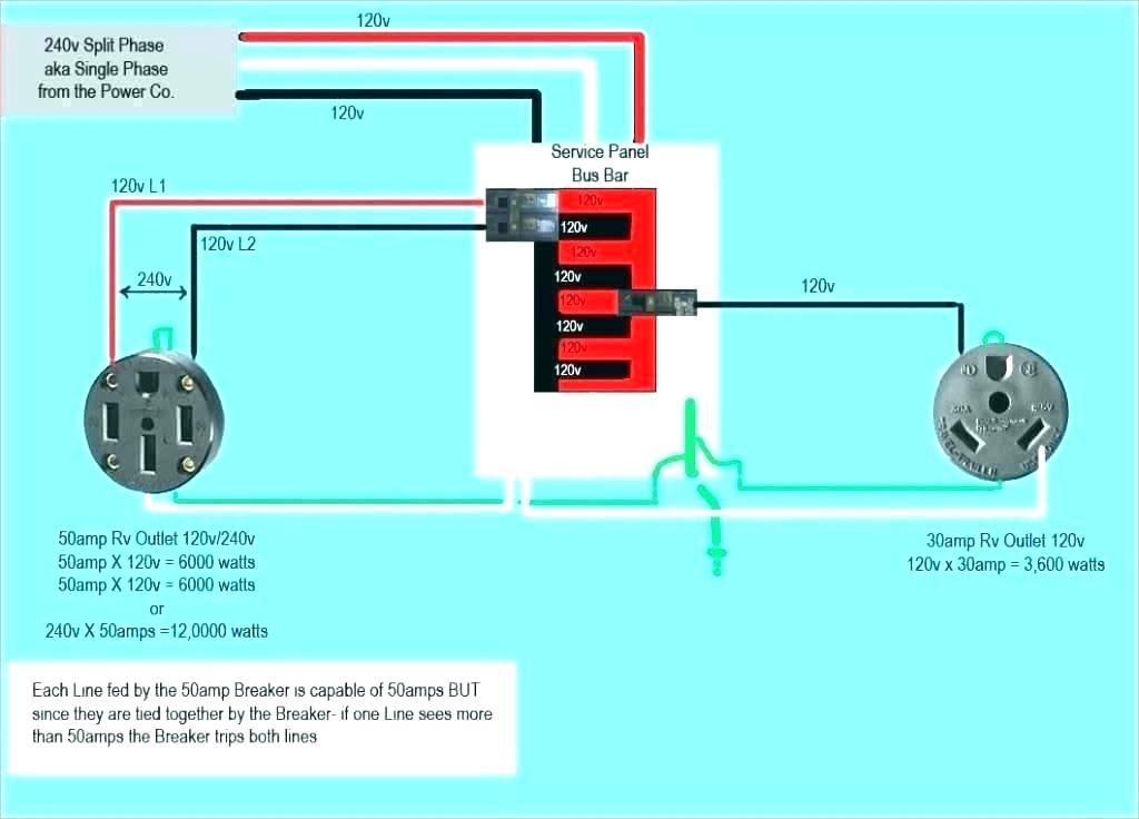
Different region-specific plug types—such as IEC 60950 standard receptacles, North American NEMA (National Electrical Manufacturers Association) profiles, or European Class 2 plugs—follow structured wiring sequences defined in their respective diagrams. - NEMA 5-15 (North America): Standard five-prong design with two hot wires (labeled “H1” and “H2” on diagram), neutral, and ground.
The orange hot, white neutral, and bare ground conductors follow strict spacing, consistent with NEMA 5-15J specifications. - IEI 16A (Europe): Four-pin EU standardized plug diagrammed with earth flag, live hot, neutral, and optional ground—diagrams emphasizing integrity of high-polarity grounding essential for safety in 230V installations. - USB-C Power Delivery (Modern Tech): While digital interfaces differ, modern schematics adopt polarity and phase emphasis, reflecting a shift toward bidirectional power and data synchronization in mobile and IoT devices.
Each wiring diagram encodes not just how wires connect, but enforces compliance with regional safety codes such as the NEC (National Electrical Code) or IEC (International Electrotechnical Commission) standards. Misinterpretation risks violations, inefficiency, or catastrophic failure under load.
Decoding the Plug Wiring Diagram in Practice
Using a plug wiring diagram step-by-step ensures safe connection of electrical devices.
The process begins by identifying the receptacle side—sometimes diagrammed front-facing—and mapping each terminal’s role. - Draw the phase hot conductor (often red or black) into terminal A. - Connect neutral (white) to terminal N and ground (green/bare) to the corresponding earth pin.
- Verify polarity: in most North American setups, hot wires are front-facing and carry “H” labels. - Use color-coded wires or label tags to avoid confusion; diagrams often annotate each wire with resistance ranges and amperage limits. - Cross-reference with local codes—some countries mandate a ground wire even for two-prong plug adaptations.
Example: Installing a microwave in a residential setting requires referencing the NEMA 5-15 wiring diagram, ensuring the five-prong plug matches the 120/240V branch circuit. Without consulting the diagram, an improper connection could overload the circuit or rupture wiring insulation.
Common Error Patterns and How to Avoid Them
Even experienced users face pitfalls when interpreting wiring diagrams.
Common mistakes include: - Wrong Phase Sequence: Reversing live and neutral inputs causes reverse rotation in motors—irreversible damage without rewinding. - Ground Misconnection: Bypassing ground intent creates shock hazards and fire risks per NEC Article 250. - Color Code Ignorance: Assuming universal color coding can mislead across regions; diagrams enforce local conventions.
- Ignoring Current Ratings: Overestimating a terminal’s capacity based on label alone risks overheating. Experts stress the importance of verifying each terminal’s function against the diagram before applying power. Seasoned electricians recommend cross-checking with multimeters following diagram guidance to confirm continuity and resistance.
Digital Advances and the Future of Plug Wiring Schemat