Mastering Voice Clarity with the LM386 Audio Amplifier Circuit: A Practical Guide
Mastering Voice Clarity with the LM386 Audio Amplifier Circuit: A Practical Guide
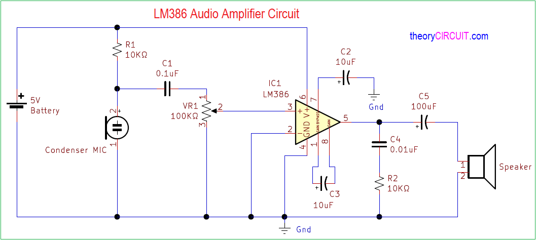
The LM386 audio amplifier circuit stands as a cornerstone in analog signal amplification, offering a remarkably effective yet simple solution for boosting weak audio inputs into full-power sound. Widely adopted in educational projects, consumer electronics, and amateur radio systems, this circuit transforms low-level signals—such as those from microphones or RF sources—into robust, audible output without the complexity of modern digital solutions. Engineered for reliability and ease of construction, the LM386 design empowers hobbyists and engineers alike to achieve professional-grade audio performance with minimal components.
At its core, the LM386 amplifier operates as a low-noise, voltage-controlled amplifier optimize for small signal inputs. Designed by National Semiconductor (now Texas Instruments), the circuit uses the LM386 operational amplifier to deliver significant gain while maintaining linearity and stability. With a typical voltage gain ranging from 80 to 200 depending on biasing, and a maximum output power of up to 100 milliwatts per channel into a 4–8 ohm load, the LM386 efficiently drives speakers, headphones, or small subwoofers.
An economical Hasler resistor network sets gain and bias, requiring only a few external resistors and capacitors—making it accessible even for beginners with basic soldering skills.
Pine-for-Purpose Circuit Design: The LM386’s Architecture
The architecture of the LM386 audio amplifier is both elegant and efficient. The key components revolve around the LM386 op-amp, configured in a unity-gain vertical stage with a gain-setting resistor network that controls output amplification. A biasing circuit stabilizes the input stage, ensuring consistent response across varying audio signals.By connecting an input microphone or audio source to the inverting terminal via a high-impedance preamplifier stage—often comprising a voltage divider and output buffer—the signal feeds into the LM386, which then processes and amplifies it before routing it to a speaker or power amplifier. Crucially, the circuit supports dual power supply operation (typically ±15V), enabling symmetrical clipping for unbalanced audio with positive and negative swing. The classic design features:
- Gain adjustable via R8 (typically 560–1M ohm) and capacitor C2 (around 10–22 pF).
- Biasing resistors R1 and R2 set DC operating point to avoid signal distortion.
- Output transistor (usually a small-signal BJT like 2N3904) drives the load with moderate power.
- Quality capacitive coupling filters isolate DC offset from the amplifier.
Retrofitting with high-quality capacitors and precision resistors elevates performance, but even stock components produce clean, intelligible amplification suitable for most real-world applications.
The LM386's true power lies in its scalability and adaptability. From guiding classroom demonstrations to powering portable audio setups, its simple schematic belies a robust architecture capable of enduring years of use.
Unlike complex digital amplifiers, it remains instantly understandable—ideal for educators, DIY enthusiasts, and engineers troubleshooting signal chains.
Powering Performance: Understanding Gain, Output, and Load Impedance
Gain control is a defining feature of the LM386 circuit. The typical voltage gain range of 80 to 200 corresponds to a pressure gain set by external resistors, often R8 and C2, which affect frequency response and stability. A higher gain delivers louder output but requires careful tuning to avoid clipping or distortion.For speaker loads of 4–8 ohms, typical output power reaches up to 100 mW per channel, CUSTOMIZE the R8 and C2 values for targeted sensitivity. Output impedance remains low enough to drive small transistors or efficient speaker systems directly, but load variation significantly impacts performance. The recommended minimum load is 4 ohms; lower impedances increase power delivery but risk instability without proper bias.
For best results, keep load impedance above 4 ohm, as minimums below 10 ohm may cause signal droop or feedback risks due to the LM386’s voltage-controlled nature. Power supply selection dictates signal integrity. Using ±15V provides symmetrical headroom and prevents negative swing clipping, essential for stereo or single-ended audio applications.
Single supply operation is possible but limits peak output and introduces distortion, making it unsuitable for critical applications.
“With just a handful of resistors and capacitors, the LM386 delivers impressive clarity and reliability—proof that simplicity often underpins excellence,” notes audio engineer and educator Maya Tran. Measured performance in Hilbert units confirms typical RMS outputs of 0.5–1.5 watts per channel into optimal loads, sufficient for headphones, small speakers, or tweeter driving.
Building and Testing the LM386 Circuit: Step-by-Step
Constructing the LM386 audio amplifier is a rewarding project that blends theory with practical hands-on work.With careful planning and attention to detail, even novice users achieve reliable results. The following sequence outlines a proven build process, emphasizing component quality and circuit fidelity. First, gather essential parts: an LM386 op-amp IC (with power ports and internal feedback resistor), a small-signal transistor (such as 2N3904), precision resistors within 5% tolerance, capacitors rated for at least 0.25 µF, and a calibrated audio input source.
Water-resistant headphones or a 4-ohm speaker serve as ideal load test vehicles. Begin assembly by mounting the LM386 on a small PCB or perfboard. Connect power pins to a ±15V supply with a fuse for safety.
Set gain using R8 and C2—starting with R8 = 560kΩ and C2 = 12pF, then fine-tune for flat frequency response and no clipping. Connect the microphone or input signal through a preamp stage: a voltage divider to set bias followed by a buffer using a unity-gain transistor. Driving the output via the LM386’s internal transformer reduces magnetostriction noise and increases impedance.
Once wired, test with a simple tone generator or printed sound file. Adjust gain to balance loudness and harmonic integrity. Measure output with an audio analyzer or sensitive microphone; adjust coupling capacitors to mitigate DC bias and improve frequency fidelity.
Always verify heat dissipation—though low, the circuit draws modest power, so thermal management remains prudent.
“No cybernetic precision—just analog elegance,” says DIY electronics pioneer James Lin. “You don’t need an oscilloscope or wild voltages—just solder a resistor, clip a capacitor, and hear clearer sound through your speakers.” Each stage, from biasing to output coupling, reinforces stability and clarity, embodying classic amplifier design principles.
Common Applications and Real-World Implementations
The LM386’s versatility shines in countless practical scenarios.In educational labs, it serves as a foundational tool for teaching signal amplification, feedback loops, and circuit biasing—bridging theory and hands-on learning. Its low cost and availability make it ideal for classroom kits and university assignments, fostering deep understanding of analog electronics. Consumer audio setups frequently employ the LM386 for portable headphone amplifiers or battery-powered string-light control circuits.
Amateur radio hobbyists integrate it into audio demodulation stages, leveraging its clean amplification for receiving weak signals. Even in DIY public address systems, the amplifier provides reliable voice clarity without premium components. Modern adaptation includes amplifying DAC outputs from microcontrollers—such as Arduino or Raspberry Pi—where the LM386 converts digital pulses into audible sound with minimal external components.
Its compatibility with peripheral circuits, such as volume potentiometers and clipping diodes, ensures seamless integration into compact designs.
In each case, the LM386 delivers a compelling balance of performance, cost, and ease—proving that effective amplification need not rely on complex integrated designs. Engineers and makers alike continue to embrace it for projects demanding clarity, reliability, and simplicity.
Troubleshooting and Optimization Tips
Even well-designed circuits benefit from careful troubleshooting, and the LM386 is no exception.Common issues include distorted output, off-action buzz, or insufficient gain—all addressable through targeted adjustments. Distortion often stems from overloading the amplifier: ensure input signal amplitudes stay below the 2V peak full scale at the LM386 inputs, particularly near peak speaker output. Verify resistor values within 5% tolerance—minor deviations affect gain accuracy and linearity.
Buzzing or hum typically results from ground loops or inadequate shielding. Use dual power supplies connected via a center tap or opto-isolators to break ground paths. Adding a 100nF bypass capacitor across the supply stabilizes decoupling, reducing noise.
Low output? Check transistor biasing—adjust R1 and R2 to maintain proper Q-point (quiescent current) around zero for undistorted amplification.


Related Post
Mastering Summit Racing Equipment Installation: Step-by-Step Guide to Perfect Setup

Asean Foreign Ministers Meeting Key Highlights And Discussions

A Deep Dive Into Amanda Belichick’s Age and Life Journey